›
›
›
High-Frequency 5G Module Interfaces
High-Frequency 5G Module Interfaces
Inside an FR2 radio, the signal has to get off the board and into a connector without losing the mmWave performance the silicon just produced. These are the board-level launches and module ports for 24, 28 and 39 GHz transceiver, beamformer and filter modules.
Getting mmWave Off the Board Cleanly
At FR2 frequencies the transition between board and connector is usually the worst discontinuity in the whole chain. These are the five things that decide how much of the budget it costs you.
Typical Interface Requirements
Figures depend on the substrate and the launch design. These are the conditions module-level mmWave interfaces are normally held to.
| Parameter | Typical Requirement | Relevant Series | Note |
|---|
| Frequency coverage | To 40 GHz / 50 GHz | 2.92mm / 2.4mm | Choose by band edge plus margin |
| Insertion loss | ≤ 0.05 dB at 6 GHz | 2.92mm, 2.4mm | Rises with root frequency |
| VSWR | ≤ 1.20 to 40 GHz | 2.92mm | Per series datasheet |
| Mating format | Push-on, full or limited detent | SMP, SSMP | Detent chosen by shock environment |
| Mounting | PCB, end-launch, flange | Field-replaceable | Rework without scrapping the board |
| Impedance | 50 Ω ±1 Ω | All precision series | Controlled through the transition |
What We Supply for Module Builds
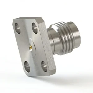
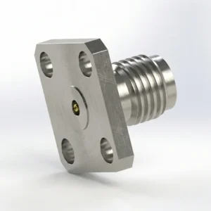
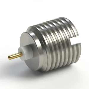
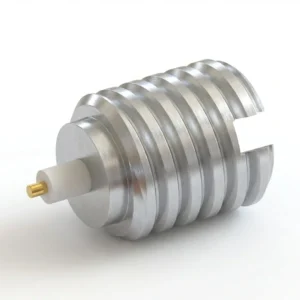
Interfaces for FR2 Modules
Typical starting points for board-level mmWave interconnect. Send us the stack-up and the band and we will advise on the launch.
Designing an FR2 Module Launch?
Send us the substrate, the band and the channel count, and our engineers will propose the interface and the footprint.