Mechanc RF & Microwave Components



- Products
- Markets
- Resources
- About US
- Contact us
X
- No products added yet.
Medical Electronics
High-Frequency RF Interfaces for Medical Imaging Devices
An MRI coil array can have sixty-four receive channels, each one carrying a signal so small that the first interface it meets effectively sets the noise floor for the image. Everything downstream can only make it worse. That makes connector selection an image-quality decision, not a procurement one.
MRI Coils
Low Noise
Non-Magnetic
64-Channel
Front End
≤0.05 dB
Insertion Loss
64 CH
Typical Array
50 Ω
Impedance
Design Notes
Protecting the Noise Floor
Five factors that decide how much signal survives the first few centimetres.
01
First-Interface Loss
Loss before the preamplifier is added directly to the system noise figure. A tenth of a decibel here costs more than a whole decibel further down the chain.
02
Magnetic Compatibility
Anything ferromagnetic near the bore distorts the field and creates artefacts. Material selection is constrained before any electrical requirement is considered.
03
Channel Consistency
Parallel imaging reconstructs from many channels at once. Channel-to-channel variation in the interconnect becomes structured noise in the reconstruction.
04
Handling Cycles
Coils are positioned on patients all day, every day. The interface is connected and disconnected far more often than most industrial hardware.
05
Cleaning Regime
Clinical equipment is wiped down between patients with agents chosen for efficacy, not material compatibility. Plating and housing have to tolerate it.
Reference Data
Typical Imaging Requirements
Device requirements govern. These are representative for MRI and imaging front ends.
| Parameter | Typical Requirement | Relevant Series | Note |
|---|---|---|---|
| Insertion loss | ≤ 0.05 dB at 6 GHz | Precision series | Sets the system noise floor |
| Magnetic properties | Non-magnetic options | Selected materials | Field distortion and artefacts |
| Channel matching | Matched across the array | Matched assemblies | Parallel reconstruction |
| Impedance | 50 Ω ±1 Ω | Precision series | Controlled through the transition |
| Mating cycles | 500+ | Clinical-duty series | Daily patient handling |
| Cleaning | Wipe-down compatible | Selected platings | Clinical disinfectants |
Our Role
What We Supply for Imaging Systems
01
Low-Loss First Interfaces
Precision connectors whose insertion loss is characterised, because at the front of an imaging chain the datasheet typical is not good enough.
02
Matched Array Feeds
Coil feeds supplied as a matched set with measured data, so channel variation does not become image artefact.
03
Materials and Documentation
Material declarations and traceability suitable for a design history file, including non-magnetic selections where required.
Selected Products
Interfaces for Imaging Front Ends
Typical starting points for imaging interconnect. Send us the channel count and the environment and we will propose the configuration.
“0.031″ Semi-Rigid Low-Loss RF Coaxial Cable, 18 GHz Rated” has been added to your cart. View cart
-

0.031″ Semi-Rigid Low-Loss RF Coaxial Cable, 18 GHz Rated
$20.00 Add to cartQuick View -
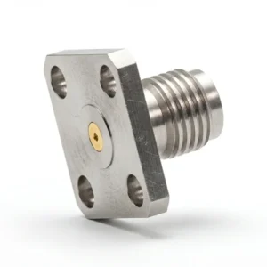
SMA Female 4-Hole Flange Mount RF Connector – Field Replaceable, 8.64mm Hole Spacing, 0.23mm Pin Diameter
$22.00 Add to cartQuick View -
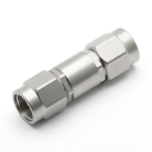
SMA Male to SMA Male RF Adapter
$22.00 Add to cartQuick View -
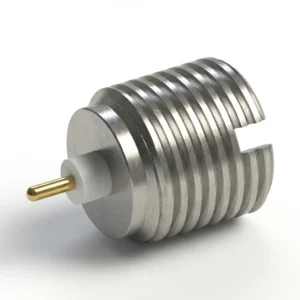
SMP Male Smooth Bore RF Connector – Stub Terminal, Thread-In, Solder
$22.00 Add to cartQuick View
Keep Reading
More in Medical Electronics
Medical Application
RF Interfaces for Patient Monitoring & Sensor Devices
Wearable telemetry and bedside monitoring interconnect.
Market Overview
Medical Electronics
The full picture: precision RF interconnect across imaging, monitoring, therapy and diagnostics.
Related Market
Test & Measurement Environments
Metrology-grade assemblies for characterising medical RF front ends.
Imaging Engineering Support
Designing a Coil Array Feed?
Send us the channel count, the field strength and the cleaning regime, and our engineers will propose the interconnect.